<-CLICK HERE FOR SCOOBY TECH. POSTS ONLY! CLICK HERE FOR GRAN TURISMO POSTS ONLY!->
1998 Impreza Turbo Project Car + Expanding WRX Knowledge Base!
Showing posts with label SL. Show all posts

Saturday, 11 June 2011

Sub/Lower Front Suspension + Engine Mount Diagram

Diagram provided on request of the front suspension/steering sub-assembly, showing the main gearbox-mount [3], anti-roll bar [14] and drop-links [24], as well as the trailing-arm and its bush-mount [7+9], which I believe are at fault.

[click for bigger]

Saturday, 22 January 2011

Steering whine and ticking noise - not fixed!

The power-steering has always had a loud whine when turning at low-speeds, but it's safe to say this has worsened over the summer, where I could hear it while turning at higher speeds - roundabouts and stuff - and the after the snowy weather the whine can be heard turning in either direction most of the time. A ticking noise has also developed under the bonnet that seems to be coming from the front of the engine.

After much deliberation we decided it must be the power-steering pump on its way out with the ticking coming from its pulley. My friends had even begun to comment on the noises so I went ahead and bought the pump along with a new auxiliary-belt and spent a Sunday fitting them. The used pump I bought was definitely newer and in far better condition than mine, but if anything this made the problem worse. As soon as I fired her up the ticking noise was back and the whine could now be heard on tickover. I revved the engine and the whine went with it like a supercharger.

I can now only guess that the whining noise is coming from the steering-rack itself, which are expensive new. I can find used ones for about £100, but they are hellishly complex to fit. The ticking noise is worse, as it could be anything - the alternator-pulley, crank-pulley, oil-pump, water-pump, even the timing belt or cam-pulleys. Unless I book the car in with a pricey specialist I may never find the culprit - and I can't replace every part on the engine.

On top of this, I'm still having to top the engine up with coolant. It's such a shame that its still losing some over several weeks and there are still no signs of a blown head-gasket, so that may very well be the water-pump too. The coolant could be ending up in the boot however, but I suspect its probably just a leak. I have taped up around the rear-lights and tightened them as far as they will go into their recess over the last few months, but it seems they are determined to keep on letting in water. My subs and amp are often running with condensation and the carpet on the sub-box had ice all over it round xmas.

To top this little lot, I neglected to finish off painting the rear wheel-arches so rust has begun to creep back on both of them and they need redoing. It strikes me that as the weather gets nicer again, the forthcoming six months are going to have to be spent on a load more repair work, rather than getting back on the mods like I desperately want to. I was hoping to get the front TEINs on, fit bigger brakes, an STi intercooler to safely up power and then concentrate on the repairs come MOT time in June, but these problems won't wait and there could be a ton more on the test.

Its a crying shame, but I've decided to quit while Im ahead and move the car on to someone who will spend time on taking it to the next level, or just wrap my pride and joy round the nearest tree. I'll be listing the car on eBay shortly and we'll see what it makes. There is also a new BMW in the pipeline...

Saturday, 15 January 2011

Replacing the PAS-Pump

I wouldn't say this was a very advanced job, but it does get fiddly working in the confined spaces so the instructions are quite detailed. Also be prepared to contort your arms into horrible positions and make sure you have a socket-set with at least 5 inches of extra reach AS WELL as a 12mm and 14mm open-ended spanner, with as low a profile as possible.

PROCESS:

1. Slide the finger-clip down the rubber-hose that enters the top of the PAS-pump. Slide the hose off the metal-pipe on the pump and plug the end of the hose.

2. Remove the two bolts holding the pulley-cover in place using a 10mm wrench, then loosen the bolt on the right-side alternator bracket using a 12mm wrench a couple of turns so the pulley-cover can be slid out. Turn the pulley-cover over and push the plastic-stud that holds the throttle-cable clip out of its hole.

3. Using a 12mm open-ended spanner, loosen the far nut on the throttle-cable where it sits in the bracket as far as it will go so the cable can be pushed back and lifted out of the bracket. Swivel the cable so it clears the PAS-pump area and fasten it with a cable-tie.

4. Using a 14mm open-ended spanner, loosen the union-bolt that attaches the metal-pipe to the port on the left side of the PAS-pump. Only crack the bolt off a couple of turns so no fluid spills, but the bolt can be removed easily once the pump is no longer fixed in position.


5. Remove the bolt that is threaded through the long adjusting-bolt that moves the alternator up and down. There is no need to slacken the adjusting-bolt - once the holding-bolt is out, the alternator should drop down fully anyway.

6. Lower the alternator until the belt becomes loose enough to be slid off the pulleys.

7. Remove the 3 bolts holding the PAS-pump in place using a 12mm wrench. There are 2 bolts to the front of the pump, beneath the pulley, which are easy to find, but there isn't a lot of room to turn them. The third, to the rear-right of the pump can be accessed from above, but you'll need at least 5" of reach on your ratchet.

8. Now the PAS-pump is free, remove the union-bolt from the pipe on the left side and lift the pump out. It's best to wrap a cloth around the union-bolt when removing the pump to catch any PAS-fluid dropping into the engine, although the pump shouldn't spill a lot anyway. **Plug the end of the metal-pipe.

9. Install the new PAS-pump, replace the pipe/union-bolt and insert the 3 bolts holding it in place.


10. Slide the new belt into position on the 3 pulleys. Lift the alternator until the belt is tense and replace the bolt that holds the adjusting-bolt in place. Now tighten the adjusting belt to the torque mentioned in the Workshop Manual [here] or just until the top stretch of the belt can be moved about 5mm up or down.

11. Replace the rubber return-hose and finger-clip to the top of the PAS-pump.

12. Snip off the cable-tie, swivel the throttle-cable back into its natural position in the bracket and retighten the 12mm nut on the far side.

13. Add PAS-fluid to the pump and allow it drain into the system and air to come out until the fluid reaches the measuring-scale on the cap.

Monday, 3 January 2011

New Halogen Spotlamp Bulb - wrong type.

Well, happy new year everyone and as I'm so desperate to get back working on the car I've kicked off 2001 by buying another high-power halogen bulb to make my old O/S spotlamp match the one I bought recently. Problem is I made a hasty choice and bought the wrong kind. Even after describing the multi-coloured type to the guy in Halfords and re-checking the colour of the bulb itself it still turned out to just be a white glow, with a little bit of blue in the middle and looks more like the one it replaced. £8.99 in the gutter. Ah well, I guess I'll have to keep looking, or just change the coloured one for the original white one I took out today.


FITTING:

Changing the fog/spotlamp bulbs only takes a minute, but its more fiddly than I expected so heres the process.

1. Remove the 3 bolts holding the spotlamp in place using a 10mm wrench.

2. Unclip the plug on the spotlamp wire and slide it free of the wiring-harness in the bumper.

3. Turn the grey seal-plug anti-clockwise until it can be lifted out of the seal. Be careful not to pull too hard on the wiring.

4. Slide the earth-wire, with the light-blue rubber-sheath, up off its mount on the spotlamp chassis.

5. Slide the end of the live wire, coming off the base of the bulb, out of its socket in the seal-plug. The socket sits in a mount and can be lifted out to make it easier.

6. Push down the metal-wire clip behind the bulb at the side nearest the gray-plastic adjustment-bracket and move the wire-clip out of its mount and rotate it out of the way.

7. Replace the bulb with the new one and reverse the process.

Sunday, 2 January 2011

Relocating the Stock-Aerial Part 1

I know Scooby's aren't designed with aesthetic perfection in mind, but its a shame they follow the utilitarian Japanese convention of bolting a tacky plastic thing on afterwards with an 80's pull-out style aerial in, usually on the driver's A-pillar. Even the 60-reg Toyota Hilux coming in at work, which are pricey trucks, still have these things and, while I'm sure they function superbly, they don't half look crap.

I've been planning to re-locate the aerial onto the roof of the Scoob for a while now and change it from a tacky telescopic metal one to a BMW-style 'shark-fin', but you could fit a rally-style mast-aerial, a bee-sting or a GPS-box lookalike in the same way. Its not a difficult job at all, but a brave enough one for me to struggle to get round to it. Doesn't look like it'll be any time soon, with all the other jobs mounting up [
power-steering is gonna need looking at first I think], but I reckon its a sound idea so I'll write it up anyway.

Removing the Stock Aerial:

Unclip and remove the plastic cover on the driver's A-pillar inside the car and cut the wires going to the aerial-mount.

Remove the two screws holding the aerial-mount with a flat-head screwdriver and prize the plastic-mount away from the a-pillar.

Bridge the holes in the a-pillar with metal-filler, or just stick about 5 layers of black-tape over the back of them, then fill the outer layer with P38 body-filler. Its only a tiny area so shouldn't be hard to sand, prime and paint-match.

Installing the New Aerial:

Inside the car, unclip and pull down the roof-lining. I'm still unclear on how to do this so, for now, refer to the Body section of the workshop manual here - http://www.scoobylab.co.cc/2010/12/manuals.html.

Find a suitable spot and drill a hole wide enough for the new-aerial's mounting-stud. Drill from the outside in and it's easy to dent the roof so drill slowly, use plenty of oil on the bit and it might be worth starting with a small pilot-hole to make sure the location is accurate.

Place the mounting-stud of the new-aerial through the hole and stick the base down onto the roof. Tighten the nut onto the mounting-stud inside the car.

Extend the cut-off wires at the a-pillar, if necessary, across the inside of the roof to meet the cable on the new-aerial and tape it into place. It's likely the new unit will have a male FM-aerial connector on it [same as the one in the dash that plugs in to the head-unit], so you could cut it off and hard-wire it, but for a nicer job I'd recommend getting a female FM-aerial socket from Halford's for a couple of quid and crimping it to the a-pillar wire. That way the aerial can be un-plugged easily if some idiot decides to nick your new bee-sting and you have to a quick replacement.

Clip the roof-lining back up into place and replace the plastic-cover to the inside of the a-pillar.

Monday, 27 December 2010

Lowering the Roof Height

Its not a mod I would have thought of for a Scooby, but I spotted this absolutely mental Blobeye STi in a mag [built by Jap shop C.S Hiro http://www.cshiro.co.jp/], with its roof lowered! I've only ever seen this done to classic cars, mainly American metal, although I've seen a few Vauxhall Victors with it done in the UK, but as it turns out the modern Scooby shares a key bit of design with the aforementioned that makes it an ideal motor to do a roof-chop on!

The Impreza has sashless-doors, which of course means that there is no frame around the window glass and that means no alterations need to be made to the doors at all. When the roof height drops, the windows will still rise up and fill the gap perfectly, with the lower part of the glass permanently sitting in the door. In theory the four windows would each fit flush even if the roof wasn't perfectly straight. Chopping the height out of 4 normal doors separately, then matching them to the roof would be a difficult task and this makes it a super-expensive job for most motors. Examining the Scoob though, it looks like all you'd need to cut are the 6 roof pillars and this makes it a much easier job, one you could do at home in fact with enough time and ingenuity.


THEORY:

Roof-Chop:

Wind the windows fully down. Remove the front and rear windscreen, along with both wing-mirror chassis, the roof-lining, a-pillar covers, parcel shelf and unbolt the front seat-belt holsters off the b-pillars.

Sand the a and c-pillars down to the bare metal.

Mark along the base of each roof pillar and cut straight through into the cabin, without deforming the metal. You could probably do it with a small grinder, but an oxy/acetylene 'plasma-cutter' would be ideal to cut a neat curve.

Lift the roof off the car. Mark around the neck of each pillar at a suitable height for the roof to be lowered by [probably about 3 ins.] and cut them again, then file down the remaining pillar ends, as well as the cut-edges on the car body, to as flat an edge as possible.

Lower the roof back onto the car, marry the pillars to their bases and weld completely around where they meet. Grind the welds down and rub them flush to the body with emery cloth. Build up around the visible joins with metal-filler and P38-filler and sand them in a smooth line between the body and pillars. Re-paint the a and c-pillars. Shorten the plastic pillar-covers to fit and replace the roof-lining etc.

Roll-Cage:

** The rigidity of the roof is probably compromised quite a bit by this process so its essential to fit a roll-cage really to stiffen things up, but primarily for safety. If this isn't a major concern you could get away with just bolting or welding in a steel-tube down the inside of the b-pillar from floor to roof.

Windscreens:

With the roof sorted, the real challenge is to make the windscreens the right length to fit. Normal Scooby windscreens are about £200+ so a tailor made narrow one probably isn't cheap, but I've found TW Windscreens in Southampton who will make one. On the other hand, I've seen cut windscreens lying around at work done using a great grinding-disc that only damages about half a cm around the line of the cut. We reckon you could cut the bottom away from the windscreen and seal the fractured edge with epoxy-resin. Then, when the windscreen is sealed in place, make a plastic or rubber sill to overlap the bottom edge [which seems to be the case on the C.S Hiro car anyway] and a smaller one for the rear.

Seatbelts:

Belts are a major safety thing, so if you've made the mounting-holes on the b-pillars too low then its worth scrapping the lap-belts and installing racing harnesses, which the standard STi and post MY96 seats will take. Otherwise you'll need to drill a new hole further up the b-pillar if possible and thread it with a fairly large tap, but the bolt might need shortening as the gap behind gets narrower at the top.


Saturday, 18 December 2010

Quick Bumper Fix

I must have got a bit over zealous on the way to work on Thursday morning [racing Big Alex in his Isuzu Trooper 3L], because my back-bumper started to make its way off the car, luckily just as we were pulling up at the gate. The small bolt that holds the corner of the bumper by the wheel-arch has broken free of its rusting mount, leaving the right-side edge hanging loose and letting the bumper become wayward. The plastic-mount on the bumper has obviously always had a break in it, probably after that wheel-arch's scuff with a gatepost, but it was still clinging on. Once the bolt had made its way out of the body though the bumper didn't put up much resistance and the bolt is long gone. All this means there's no meat left to get a cable-tie round so I had to just drive carefully and pray the bumper didn't drop completely before the fix.

Everyone suggested just banging a self-tapping screw through into the metal, but that'd be too easy and no good if I need to take the bumper off in future. Instead I rustled around in the ever fruitful skip for a few minutes and found a nice allen-head bolt, two shiny washers and a brand new nyloc-nut. Outstanding. There's another small hole in the bumper just behind the split one, so I marked where it meets the body-lip and drilled a 5mm hole through the metal. Even with the car tilted on the curb I could barely get my hand into the gap between the tyre and wheel-arch, so I could barely hold the allen-key steady while I got the nut on. In the end I just managed to get the nut a few turns into the nylon, but enough to keep the bumper on until today when [with no help from the weather!] I got the wheel off and tightened it up.


>>> Oh and yeah, I do notice that the rust has creeped out from under the wheel-arch. There's a bit of bubbling too so both arch-lips are going to need rubbing-down and spraying again as soon as the weather turns reasonable, just hope it doesn't get much worse in the meantime. The moral of the story here kids is ALWAYS lacquer as soon as possible after spraying and wax-oil/seal the underside if its somewhere like the wheel-arch! Nightmare.


Saturday, 11 December 2010

Carbon Conundrum + Bodywork Update

Spotted this amazing 100% carbon-fibre bodied, Japanese-built Blobeye STi in a mag at work - yeyah! It's got me thinking about carbon again, but I've only got a small patch of the stuff left [about 12x12ins.], which wouldn't even cover a wing-mirror, so I'll have to find something small to fab-up while the weather is too cold to move forward with the car itself.

I have thought about styling, but so far the favourite option is to finish off my alloy-plate cold-air shield with carbon instead. I do have the plate pieces cut and getting hold of a TIG-welder [special light-metal welder that doesn't just rip alloy apart] was something I dearly wanted to have a go at, but to fill the winter gap and get on I may as well bring some more carbon to the engine bay.

And I must finish that darn wind-diffuser!! SHEESH!

** Also I'd like to say a massive big-up to Dave from Howarth's Bodyshop in Pensby [who do various bits on our firm's vehicles] for passing on a couple of cans of Zinc-Primer [which I never have enough of] and Filler-Primer, which I've not used before. Apparently it's the mutts-nuts for filling in the tiniest gaps and smoothing the paint-surface, so we'll have to give it a whirl if I find time to re-spray the wheel-arches. Respect! Will have to ask Dave about spraying my black front-bumper silver so I can replace the damaged one... **

Thursday, 2 December 2010

The 'Black Socket Trick'

Machines that read fault-codes aren't cheap, starting at about £350 and running into thousands for a pro one, so its good to know that Subaru, like a lot of other Japanese marques, builds in a gizmo that lets us check the codes ourselves, at the roadside if we need to.

There is a male and female plastic connector hanging loose just behind the trim under the steering column, just behind where the socket for the OBD-type reader is. The connectors are unplugged from each other by default and clipping them together bypasses the circuit for the OBD socket so the car's own can be used.

Once the two connectors are clipped together, turn the key so the ignition is fully on, without starting the engine. The CHECK ENGINE light will do a series of long and short flashes. First come the long flashes [about 1 sec each], which denote the first digit of the fault-code and then quick flashes, which denote the second digit. i.e two long and three short would be a fault-code 23.

Here is the LIST OF FAULT CODES that work with the system.

[The car still works with the connectors left plugged in, but its probably best to unplug them to save the car doing a check every time you start up and make the OBD socket accessible if you take the car in to a garage. Not that any ScoobyLab fan should ever have to!]

Sunday, 28 November 2010

Wing-Mirror Fixed!!

The wing-mirror had obviously been knocked off at some point in the past and it was held on a by a massive wrap of strong tape that looked ghastly. I recently decided to replace that with nicer looking black-tape, but it just wasn't up to the job. Rather than chuck loads more tape on I decided it was time to just bite the bullet and fix it as I can't lacquer the car this weekend.


The metal mount has sheared clean off, but there's no damage at all to the wing-mirror casing and the electric swivel still works so it seemed a bit of a waste to buy a whole new unit [starting at about £30 on eBay for a used one] when there's probably a way to fix it. The metal mount is only alloy so I figured it wouldn't be hard to drill a hole in both parts and get a bolt through. There's plenty room in the casing to hide the bolt and for a real tidy touch I drilled through one of the existing screw-holes on the door-mount so the bolt-head is also hidden away, which also made drilling a lot easier. The screws only hold the plastic-casing onto the mount and there are 3, so I think I can afford to lose one.


Hiding the bolt-head means the work I've done is invisible, but I had to use a 4mm bolt to fit the head up into the existing screw-hole. Even a slim steel bolt won't snap easily, but I would have liked to use a fatter one just to reinforce against those wheelie-bin knocks as it can't swivel inwards, but it couldn't with the black-tape anyway so I'll have to carry on being careful. I was beginning to think the job was suspiciously easy when I hit my first snag - tightening the bolt without the nut spinning around. To do this I had to remove the mirror-glass and motor-bezel to make a small gap to slide a spanner through and grip the nut. The plastic around the nut was still very constricting and the spanner had to be poised perfectly on the edges of the nut to get a few turns before it gave and had to be repositioned, which was frustrating but I got there in the end so money well saved.


As you can see from the ice on the windscreen my fingers were numb and blue but I think it was worth it to finish both this and the spotlamp in one weekend. It may not swivel or be as sturdy as a replacement, but its just as good as the black-tape and the mirror looks positively brand-new, so if it lasts me for as long as I have the car then result!

Saturday, 27 November 2010

New Spot-Lamp Sorted!!

Wow, the weather really has turned bitterly cold this week and spray-work is out of the question. I think that to get the lacquer on before xmas now will need somewhere indoors to do it, but I did find a real spot-light this week to replace the fake one so, even though my fingers were numb and purple I just had to get it on. After all, we might have fog again tomorrow...

A while ago I got hold of a replacement front-bumper from a mint import car and luckily it holds the bracket I needed for my missing spot-lamp, which made finding the new one much easier. I will be replacing the whole damage-repaired bumper eventually, but the new one is black so I'll have to get it painted first, its a bit too big a spray job for me I reckon.

The spot-lights haven't been cheap on eBay lately, with a few on for £40+ and loads of pairs starting at £70. The lenses have Subaru etched along the bottom and the back of the lamp is angled, so you can't switch sides and have to rely on finding the one you need. I spotted a near-side one for £30 delivered from smr-subaru and thought what the hell. It took a week to arrive, but its in great condition [much better than my current one] and has a blue/rainbow type halogen bulb in it, which is nice, although I'll have to buy a matching one for the other side!


FITTING:

All 3 of the bolt-holes in the old bracket had broken off studs in them so the whole thing had to be replaced, but luckily the bracket just slides down off hooks and can be lifted out without removing the bumper. It slides out between the gap in the bumper corner so the under-tray doesn't even need to come off. The old wiring socket for the spotty has been hanging loose next to the wheel-well, so I gave it a good clean out with brake-cleaner and electrical solvent before plugging in and testing. The new bracket is off an import too and as you can see from the pic its in great condition with perfect threads so I bolted the new lamp in place with 3 more of those trusty alloy allen-bolts from the skip at work. The top-right bolt also holds the corner-indicator in place again, which is great as its been held on with a giant ball of ally-tape sincebefore I bought the car. I'm chuffed to bits to have this boxed off at last, the car is starting to look a lot less ratty - just gotta fix that broken wing-mirror and the body is complete!!

Saturday, 20 November 2010

N/S/R Wheel-arch Touch-Up

There's always been a few bubbles in the paintwork just behind the near-side rear wheel-arch, but they have grown a little bit over the year. Last week I pressed the blisters a bit and dirty water dribbled out so I decided it was best to act on the corrosion fast before the worst of the weather hits. I really should lacquer the work I did in June on the off-side rear wheel-arch when I finish this side off too, it shouldn't have been left so long - the paint is holding up so far, but best not to chance it with frost round the corner.

I started by carefully breaking the bubbled paint off with a sharp knife. The paint and primer had bubbled clean off the metal panel and was quite tough to break off still, but a few weak spots were obviously letting nasties in and there was just a little rust beginning under the lip at the bottom. Luckily the panel itself was holding up pretty well and wasn't showing any signs of actual rust, but there was lots of black pitting that went down quite deep into the surface.

I then rubbed down the area about an inch around the corrosion with 140-grit paper to get rid of the paint. The black pitting was a different story and it took quite a bit of rubbing with emery-cloth to get down the clean metal. I was still left with a few deep craters, so I managed to eek out one last mix from my tube of P38 filler and did a thin skim over the whole area to make sure even the smallest pits were filled, before sanding it flush to the metal. I then threw on a quick coat of zinc-primer and sanded it flush with some 600-grit Wet/Dry paper soaked in slightly soapy water, so I don't get panty-lines in the paint. I did start spraying the silver-coat on Sunday, but got a bit over-zealous and the paint ran something awful. Its back to work I go too, so I'll have to give it a quick rub down and finish the silver-coat next weekend, as well as lacquering this and the other wheel-arch - lets get some closure on the spray-work!!

More detailed descriptions of the rubbing, filling and painting processes can be found in the previous posts Painting the Bonnet Lip and Re-Inventing the Wheelarch Pt. I.


Saturday, 6 November 2010

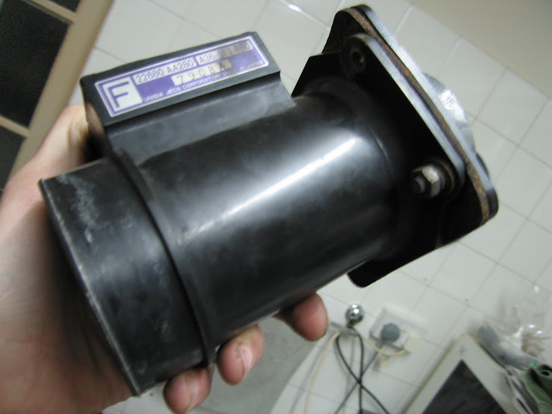
Return of the MAF!! - Sensor Replaced!

It's less than a week since the car died and I've managed to get her up and running again, thanks mainly to a lot of help from the ScoobyNet massive. I really thought it was curtains this time - the car just seemed so poorly on Tuesday, coughing, spluttering and idling so crazily - all the signs of a generally broken engine and I would have never have known where to start diagnosing it without all the help and advice from the forum and its free - diagnostics are renowned for running up huge bills at garages, so the Scooby community really is worth its weight in gold.

With the mechanics at work all pointing to a broken head-gasket, I nearly started the horrible job of ripping the engine apart, but now I've discovered the black-socket trick for reading your own fault-codes, [which I will have to cover properly in its own post soon - I've never seen anything so trick!] I know I won't be needing dodgy opinions in the future. Much better to get info from people who know their Scoobys inside out!

By Friday I'd got in touch with a lad on eBay called BigEd4244 who had a couple of Purple MAFs for sale, and asked me to make him a serious offer. I said £70 and he messaged back to say he'd take £90 and send the unit next-day delivery, so I agreed and sure enough the MAF was waiting for me when I got home on Saturday. Fantastic, helpful service! A new one of these would set me back £289, so mine would have been literally cheap at twice the price.


Fitting it couldn't be easier. It's held in place by one of the bolts that hold the top-hat adaptor for the air-filter, which is fine if you have a cone like me, but getting the bulky, standard air-box off is a bit more involved, so check page 2-7 [W1A1] in the Subaru Workshop manual [download here] if you do have the latter. This process is the same for all Classics after MY97.

PROCESS:

1. Disconnect the battery earth-terminal.

2. Unplug the wiring-socket from the near-side of the MAF-unit by depressing the clip and sliding it out.

3. Remove the air-filter by undoing the jubilee-clip with a screwdriver.

4. Remove the four bolts holding the top-hat adaptor for the filter onto the MAF-unit using a 10mm wrench.

5. Undo the jubilee-clip holding the MAF-unit to the turbo-inlet hose and gently lever the MAF-unit down into the gap below until it breaks free of the rubber-hose.

6. Wipe around the mouth of the rubber-hose and the terminals on the MAF wiring-socket and reverse the previous 5 steps to install the new MAF-unit.

I am now reveling in smooth-running bliss. The engine feels so content through the rev-range now that I can't help wondering if the MAF-sensor has been on its way out for a while, becoming more and more noticeable with the cooler weather. I'm well annoyed that this £90 couldn't have been spent on improving the car elsewhere, but I guess keeping it on the road comes first. Cars eh?

Wednesday, 3 November 2010

MAF Sensor Trouble, Car Dead!

Oh my days, I've had so little to do on the Scoob lately that I have almost willed something to go horribly wrong. And it has. The MAF [Mass Air-Flow] sensor, which sits just behind the air-filter and gauges the amount of air coming in to the engine so it can prepare the right amount of fuel, looks like its thrown its hand in suddenly and for no good reason. Its a notoriously hard to come by part too and the worst bit is my baby is off the road until its fixed. Oh well, I was hoping when I did get working on the car it would be to upgrade it, but hey ho :)

FAULT FINDING:
The car started juddering on Monday morning at about 2500 revs so I let it warm up and it was fine so I put it down to the cold weather, but the judder has continued to get worse. When the turbo was kicking in the engine was going to pieces. Once the car was warm though and I managed to get past the rev barrier, the turbo was running fine.

I asked around on ScoobyNet and everyone suggested the MAF sensor, but to know for sure I'd need to plug-in and read the fault-code. I don't have a diagnostics-setup to hand myself, but I was amazed to find that Subaru have a built-in workaround for the layman. Under the steering-column, behind the dash, are a couple of black wire-connectors. When they're plugged together and the ignition is turned on the Check Engine light will flash a sequence like morse code. The series of long and short flashes corresponds to an error-code - a seriously cool bit of gadgetry that! I got 2 long and 3 short flashes, which is a code 23 and, of course, the MAF-unit. http://www.scoobypedia.co.uk/index.p...odeDefinitions

At the time that sounded great because I was fearing a blown head-gasket again, but its turning out to be a right bugger to get hold of. There are quite a few types of MAF-unit for the varied Imprezas and you have to get the right one. Each model variant has a corresponding coloured label on the MAF and most people were telling me to buy an Orange one so I had to get mine off to see.


Lucky I checked as it turned to be a purple one! I'd found someone with an Orange one to sell me for £70, but it looks like the Purple is a more elusive chap. ImportCarParts do have a few brand new Subaru's own Purple label MAFs in stock, but you pay for the convenience at £289!!

I've made my plight known on ScoobyNet and it seems the purple MAFs are popping up often enough so we'll have to wait and see what comes up because I just can't afford to shell out another 3 ton on repairs this close to Xmas.

*UPDATE!* 6/11/10 - I have obtained a purple-label MAF unit and it seems to have done the trick thank heavens! Info + How-To is in this post - MAF Sensor Fixed! Phew!

Sunday, 10 October 2010

Bolting down the Passenger Footrest

The alloy-plate in the passenger-footwell has become an annoyance as people always seem to find a way to kick it around and wedge it under the seat so its time to fix it in place. I've been hesitating because I'm reluctant to start drilling holes and screwing through the cabin-floor in case I hit something like wiring or a fuel-line, but it turns out that floor carries on flat to the engine-firewall and the bit the slopes up for the footrest is just a thin steel false-floor.

I think it's worth noting in case I decide to remove the heavy false-floor later and completely replace it with my slimline alloy job when I decide to get the weight down. It's only held in place by 4 bolts and I don't think it stiffens the body enough for the softer metal not to work just as well. For now though I've just plonked the alloy over the top. I took one bolt out from each side of the false-floor and fixed down the alloy-plate through the existing holes with 2 more allen-head alloy bolts. I countersunk the holes in the alloy-plate, but the heads are quite deep so they only fit flush to the bumps not the plate itself.

Monday, 27 September 2010

Painting the PAS-Fluid Cooler + stuff

While I had the radiator out I noticed that the cooler for the power-steering fluid was a bit rusty. This is basically a pipe that runs along the front of the radiator, catching the incoming air and cooling the fluid inside, but its obviously caught its fair share of salty crud over the years too.

The pipe is still sound and the cooler still works of course, but I thought it best to give it some fresh protection while I had the chance. I scraped off all the surface rust, gave it a good rub down with emery-cloth and wiped it off with a damp cloth. I then gave it a good, thick coat of black Hammerite. Shame about the hammered finish, I'm sure I had some black Smootherite lying round, but its high-heat resistant none the less and looks a damn sight better.


While I was at it I thought I'd spruce up the battery tie-down as well and finished it off with two nice, shiny new nuts. Every little helps!

Sunday, 26 September 2010

New Koyo Alloy Radiator

FAULT FINDING:
I check the coolant level reasonably regularly, but one night the temperature-gauge went upslightly over the norm and after a while kept on rising so I banged the heaters on full blast and managed to limp the car about 2 miles home. Next day I discovered that the coolant had nigh-on disappeared! I filled the system back up with water - it took about 5 litres - to check for system failure and ran the car fortheweek,butthewater level stayed up and no sign of a leak. With no obvious evidence of failure my dad immediately suggested the head-gasket was blown and the coolant must have slowly gone through into the cylinders :( The mechanics at work backed up his claim and said that, because of the boxer-engine with a cylinder-head down either side, it was a nightmare job that needed the lump lifting out to do. I reckon I could do it without lifting the engine, but it would involve removing almost every other item from the engine bay. Rather that though than forking out for a professional to do it - I shudder to think how much that would cost. This could have been a killer blow for the Scoob, but all the other symptoms of a blown head weren't there - no oil in the water, mayonnaise in the oil, loss of power or rough-running.

At this point, with the levels staying up in the header-tank, I had to add coolant to the system to stop it rusting up, so I drained the water out, flushed it out with more water to get rid of any floating crud and re-filled it with a half and half mix of water and 3L of Halford's Advanced engine-coolant, which wasn't cheap at £24 (£7.99 per litre). I then checked the header-tank daily for a week with no change in the level.

Another two weeks of harder driving went by and I checked the coolant again. This time there was a definite drop in the level - the tank was only about a quarter full so I'd definitely hit a problem. Now I spotted the radiator. Its always looked battered but showed no signs of being split - I guess the old leaking coolant couldn't be seen as well as the fresh bright-pink stuff. By the look of the pink patches though, the radiator had burst in three places so it had to be replaced asap and I didn't know whether to be gutted over this or elated that it wasn't the head gasket...

NEW RADIATOR:
I had intended to put an all-alloy racing radiator on at some point, but these cost £130-£300 so to fit one now would kill my chances of buying brakes and stuff any time soon and I've got to move forward with the car. The OEM-spec radiators are all-alloy themselves [although not as chunky obviously and in a mild-steel surround] and less than half the price so it was a no brainer really to get the leak fixed. I scored one for £50 including next-day delivery off a guy called [dilley3613] on eBay - laughing. It's no cheap Chinese piece either, this is made by Koyo in Japan and, although its not quite as sturdy as the original one, its still looks a decent-quality part.

Fitting it was not a hard job at all. You only need a couple of spanners and there's not a lot to undo. There's plenty of space to work in a
nd the radiator lifts out clearly. Our only setback was the two bolts holding the radiator top-mounts were rusted so tight they snapped on the way out so we had to drill through and put a new bolt in with a nut underneath, which took ages. The top-mounts are all that hold the radiator on so check them for rust and WD40 them for about a week in advance to try and avoid the hassle.

PROCESS:

REMOVAL:
1. Jack the car up and remove the front under-tray by the two 10mm bolts on either side and the two 12mm bolts front and back. Lower the car.

2. Remove the radiat
or/header-tank cap to release pressure from the cooling-system.

3. Drain the cooling-system by placing a plastic-tube over the spout of the drain-valve at the bottom left of the back of the radiator and opening the valve. Drain into a clean bucket if you're re-using the coolant as I did and cover it straight afterwards.

4. Disconnect the fan wiring-socket by sliding a screwdriver down the slot in the connector until the two sides can be pulled apart.
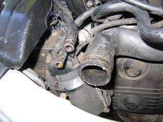
5. On MY97/98 model cars the overflow-pipe from the header-tank is a thin metal tube that runs along th
e top of the radiator - later models won't have this. Disconnect
the overflow pipe from the system by removing the finger-clips and sliding off the rubber-hoses at each end.

6. Disconnect the rubber-hose from the overflow pipe at the top-left of the r
adiator by removing the finger-clip and sliding it off.

7. Disconnect the two large hoses from the top-left and bottom-right of the radiator by opening up the jubilee-clips with a flat-screwdriver. They will be sealed on tight, but should wiggle off easily once the seal is broken by pushing against the edge gently with a screwdriv
er. [It's worth putting a tray underneath the lower hose when you disconnect it as there will be a bit of coolant still pooled down there.]

8. Remove the two 12mm bolts holding the radiator top-mounts in place and tilt them up out of the bushes on the radiator.

9. Now the radiator can be tilted back, remove the single 10mm nut holding the PAS-fluid cooler in place. This is the two pipes that run over the radiator and
down the front. There is no need to disconnect the hoses from the PAS-coole
r as it can be tilted well clear for the radiator to be lifted out.

10. Slowly lift out the radiator, working the lower-bushes clear of their mounts.

11. Separate the fan and overflow-pipe from the old radiator by removing the two 10mm bolts at the bottom of the fan and the three 10mm bolts along the pipe at the top of the radiator. Also remove the top and bottom rubber-bushes to be reused.

REFITTING:
12. Bolt the fan and overflow-pipe to the new radiator using a 10mm wrench and re-insert the top two rubber-bushes.

13. Replace the bottom bushes to their mounts on the chassis. [The pins on the radiator are easier to use as a guide than putting the soft bushes on first and having to force them in.]

14. Lower the new radiator into the engine-bay, pushing the guide-pins firmly into the bushes.

15. Bolt the PAS-fluid cooler back into place, with the pipes over the radiator, using a 10mm wrench.

16. Push the pin on each top-mount back down into the bushes on the top of the radiator and replace the two 12mm bolts.

17. Push the two large rubber-hoses onto the new radiator [a tiny bit of washing-up liquid might help] and tightly secure them with the jubilee clips.

18. Push the rubber-hoses back onto the overflow at the top-left of the radiator and either end of the header-tank overflow-pipe. Replace the finger-clips.

19. Refill the system with 6.5 litres of a half water/half coolant mixture using the spout next to the battery or the header-tank and letting it run through.

20. Replace the header-tank cap and the front under-tray. You're done!

Tuesday, 21 September 2010

Carbon Fibre - Rear Wind-Diffuser - Part I

With the mould looking pretty good it was time to look at the different types of carbon-fibre covering to wrap it in. There are dozens of stick-on imitation carbon sheets available, but I didn't want it to look fake even under close inspection so I had to go for real stuff. I've seen people making real carbon parts for ages and it doesn't look too hard, but the price of it used to be outrageous. Not any more it seems, as I've found sheets of all sizes of raw carbon-fibre on eBay, often being cheaper than vinyl stick-on sheets of the same size! My diffuser is about 60cmx40cm and I didn't want to worry about matching the weave up with separate sheets, so I went for a half square-metre to cover it in one go, which worked out at £19.50 delivered for 100% twill-weave carbon, whereas the 3M-vinyl sheet that contains no carbon at all [but does look a LOT like it] was £27.99 delivered - nearly a tenner more expensive! Needless to say I went for the real carbon - from a firm called [grp_supplies], unfortunately no longer trading under that name and I can't find the new one on eBay :(

OK, so I had to buy some clear epoxy-resin to set the real fibre as well and it turned out to be dearer than I imagined. I could only find small tubes of the stuff for less than ten quid, but the amounts [and the cost] jumped up massively after that. I needed quite a bit for the diffuser too, so I grabbed the best deal I could find - 1kg of resin and 0.5kg of hardener for £28 delivered, which was good value even though they arrived in unmarked and unsealed bottles. They work great though - from a firm on eBay called [CreativeResinSolutions].

I originally intended to just cover the stiff plastic mould and re-fit it, but the carbon provides its own stiffness so the weight of the tough plastic van-undertray just seemed unnecessary. The thick plastic must weigh a couple of kg on its own so even the spaceship-light carbon would be a useless increase and the back end is already well planted with that soundsystem...

This meant I had to get the carbon off the plastic after it had set, which turned out to be stupidly simple. A professional would, of course, produce a fibre-glass cast of the part and use it as an inward-mould for the carbon. Not only would this mean forking out more money, I'd also have to completely re-design the fins on my diffuser so, with the carbon already there, I thought of a workaround, which I'm sure would be howled at by any respectable composite-engineer, but here is how I prepared the mould - after a few tests on a small dash-panel [here] I found this to be the easiest way of quickly fabbing up my carbon part :

PROCESS:

1. Smear the part in a thin film of vaseline. Apply a layer of cling-film to the part, sticking it in place with the vaseline. Repeat the process for several layers of cling-film.

2. Mix a good chunk of 2 parts epoxy resin with 1 part hardener and wait about 15 mins. until it starts to go tacky.

3. Paint a thin layer of the epoxy over the cling-filmed part.

4. Slowly drape the carbon-fibre sheet over the part and press it into shape. The tacky resin should make it easier to hold things in place. Tightly fold the fibre over the edges of the part and tape them in place on the back.

5. Mix some more epoxy-resin and immediately paint a good thick coat over the part, leaving it to dry for at least 8 hours.

**The part should pop easily off the mould by this point once the edges are trimmed and most of the cling-film can be peeled off. You can keep them together until the part is finished, but there is probably a higher chance of it bonding to the mould.


6. Give the part a quick sand with some rough paper. Remove any sharp points, resin drips and bumps. Don't worry about making the surface too even yet, but try not to go down into the carbon.

7. Mix more resin and apply another thick coat to the part, leaving it to dry for at least 24 hours this time. [One nice, thick coat should do it, but repeat process 6 & 7 if it looks too thin or uneven.]


8. Sand the part down to an even[ish] coat, then use finer grade papers to give it a smooth surface and apply the finishing touch to best show off the weave - either a coat of normal car spray-lacquer for the wet-look, or using T-cut / rubbing-compound to buff it to a dull racing-car shine.

As you can see I only got as far as the final coat. I've rubbed it down a bit, but still haven't found time to finish it, so I'll have to cover that in another post.

All things considered though, not a bad try for a beginner! It certainly looks the part - the carbon weave looks very authentic, but the dodgy moulding technique does have it's pitfalls. The heat of the epoxy drying causes bubbles in the cling-film to expand, which doesn't affect flat areas, but has made the back-edge of the diffuser a little sloppy round the fins, although it has given the skinny fins a nice rounded profile. A pro-diffuser would cost most of a grand remember, so for about £20 and a couple of afternoons work I think its turned out superbly! We'll have to wait and see if its a go when its finished and fitted.
 
ScoobyLab + Propjam 2010/11